 Views and opinions of the author are independent of employers past or present. Duh...
A certain Rice Cooker has been languishing in a box for the last several years - now it is time to revisit it. It is a tale of Solder, Software, and Streptococcus thermophilus.
“Last time, on Rice Cooker Adventures”
This story picks up where I left off 3 years ago - the rice cooker has thermistors taped to the bottom of the pot with high temperature fiberglass tape. Specifically, I have 4 of the same thermistor in 2 parallel lines of 2 series resistors, like so.
This serves to roughly average the resistances, to account for possible hotspots on the pot, while only taking a single ADC pin.
However, time has not been kind to my memory, and the specific parameters of these thermistors are unknown, so first, it’s time to do some testing.
Side Quest: Thermistor Calibration
I have a thermocouple that I can use to verify the temperature of the pot with, so here is the setup: log the resistance through the thermistor bank at close to room temperature, rolling boil, and a middle temperature (during cooldown). These three sample points may then be used to find the parameters of the thermistor exactly.
From hazy memory (and counting parts in inventory), my suspicion was that I had used a thermistor. Brand is unknown, but representative datasheets online cite a value of 3950 - let’s see how we compare.
Wait, what does mean?
For a more in depth read, look here, but in summary early studies proposed that for NTC thermistors, the temperature could be determined given a measured resistance , coefficient and reference resistance and temperature , like so:
While this may work for small temperature ranges (approximately or so), we require a larger range, and so we are instead going to look at the…
Steinhart-Hart Equation
Briefly summarizing Wikipedia, the equation states:
Which, when using 3 sample points, results in:
In my case, I found the points of reference using a setup like so:
 Do note that in order to reach a full boil (and on the thermocouple), the lid of the rice cooker was attached.
While I could show the calculations, and they wouldn’t be difficult, I’ll be honest: I used an online calculator.
 Using the measurements:
Yielded
As we can see then, the actual value is larger than predicted ( predicted vs. actual), as is the reference resistance ( predicted vs. actual). In fact, neither of these are even in the commonly stated “” range. Good thing we’re calibrating, hey?
“Back to our regularly scheduled programming”
How to use this data then? Being short on time, I opted to take the easy way out, and use the wonderful ESPHome, as I already use Home Assistant. As it turns out, they already have us covered, with a NTC Sensor component already built in. This, coupled with a resistance and ADC sensor allow using a voltage divider to measure the resistance of the thermistor.
You know those calculations and equations we did above? Unnecessary, all of it. ESPHome supports doing Steinhart-Hart calculations itself, and only needs the three sample points.
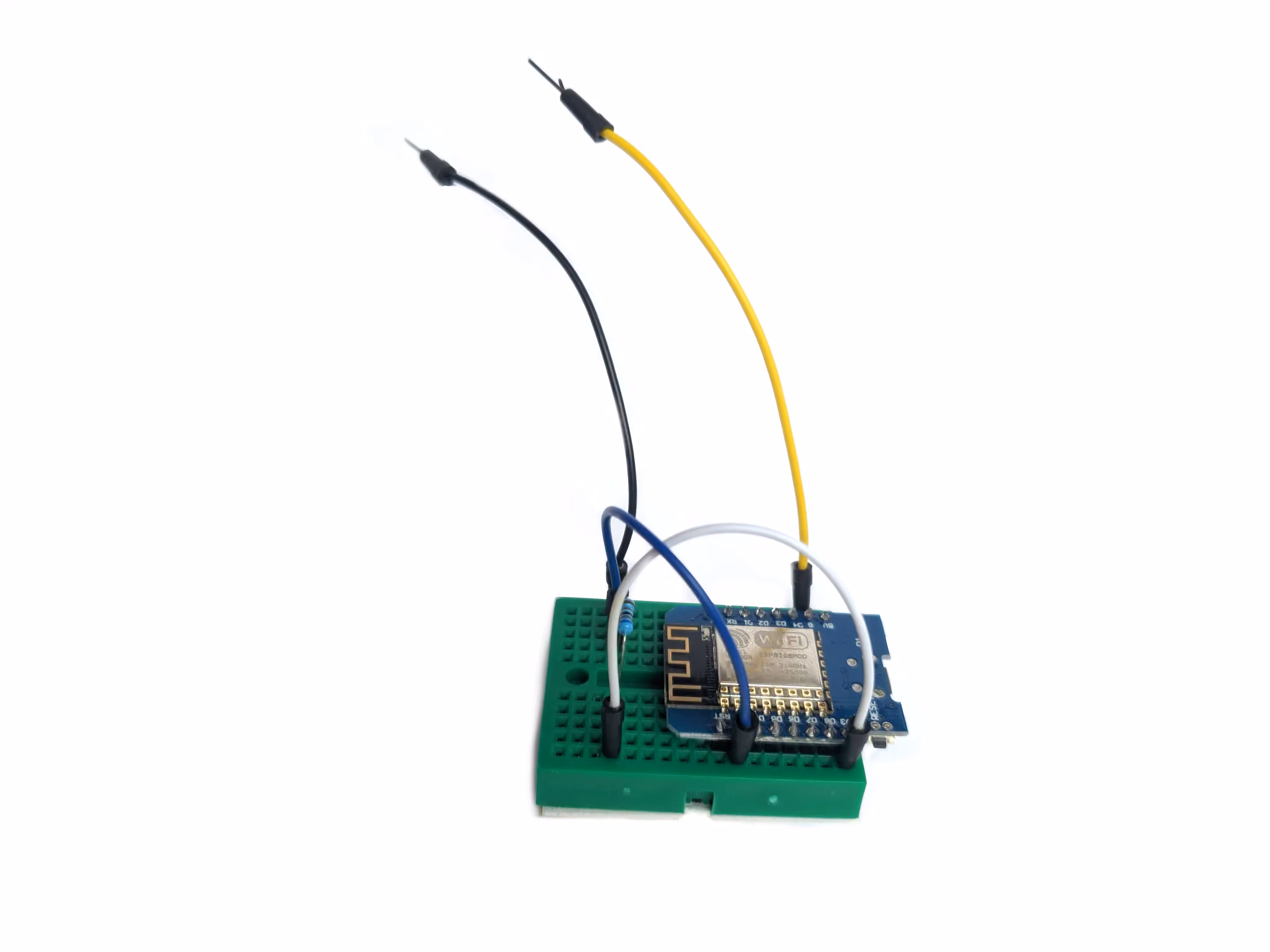
In the meantime, a Wemos D1 Mini on a breadboard is ready to go (they’re cheap and cheerful). I wire it up with a resistor (what I had handy), and away I went. The circuit looks something like this, where the two trailing wires connect to the thermistor bank:
 To prevent confusion, here is my final working config, then I’ll explain.
sensor:
  - platform: ntc
    sensor: resistance_sensor
    calibration:
      - 81.0kOhm -> 33°C
      - 21.3kOhm -> 66°C
      - 6.4kOhm -> 100°C
    name: Rice Cooker Temperature
    unit_of_measurement: °C

  - platform: resistance
    id: resistance_sensor
    sensor: source_sensor
    configuration: DOWNSTREAM
    resistor: 6.96kOhm
    reference_voltage: 3.306V
    name: Resistance Sensor

  - platform: adc
    id: source_sensor
    pin: A0
    name: Voltage Sensor
    filters:
      - multiply: 3.2
    update_interval: 1s
Calibrate all the things
Series Resistor
Easy, measuring mine I found it to be , certainly different from the it’s meant to be. Throw that in the config.
Reference Voltage
This is also easy enough, measure the pin off the D1 mini. Mine came out to be , respectably close to rated! That goes in the config too.
Multiply Filter
As it turns out, the D1 mini has an internal voltage divider to convert the of the input voltage down to the the ADC is rated for. This is nice, as it protects the ADC, but it must be accounted for. But there’s a catch - on my board this wasn’t quite right - the voltage read was still slightly wrong. I could try manually tuning this, but there is an easier way. Instead, I measured the actual voltage (), and compared it to the voltage being read.
Say there was no error, then we would say , and if there is an error of a multiple difference between the two, we can say . Thus, to find this multiplier, we say:
Using this method, I find my multiplier to be , not .
With that, the board is finally reading the correct voltage, the correct resistance, and the correct temperature.
“You’re so controlling!”
Given that I have Home Assistant, automating it becomes easy.
I’m currently using a Tasmota flashed smart outlet to control the power to the heating element of the rice cooker (for reference, it pulls up to at full load). In future, I would like to condense all functionality into a relay controlled directly by the ESP8266, to allow greater safety in case of network issues or even local PID tuning.
I am also using a PID controller for Home Assistant. It seems to work fine, I am just bad at PID tuning, so results may vary depending on hardware, amount of mass in the cooker, ambient temperatures, etc. That being said, a simple automation to turn the heater on when the PID response goes high and turn off when not high yields acceptable results.
From fiddling with the settings, I currently am using the following parameters:
Further tuning is required, but this held well overnight - mostly…
 I did change the set point from to halfway through, as well as tweaked some of the PID tuning.
The concerning spike at 9:00 is marked by a momentary loss of connection with the ESP board - my automation failed to account for a loss of connection and so allowed the heat to continue rising.
Thankfully, this was a short-lived event, but it is concerning nonetheless, and will require testing of my automation to prove that power loss tends towards a “safer” outcome.
Do note that “safer” means no dead yogurt culture - the safety features of the rice cooker remain unchanged and functional.
I did change the set point from to halfway through, as well as tweaked some of the PID tuning.
The concerning spike at 9:00 is marked by a momentary loss of connection with the ESP board - my automation failed to account for a loss of connection and so allowed the heat to continue rising.
Thankfully, this was a short-lived event, but it is concerning nonetheless, and will require testing of my automation to prove that power loss tends towards a “safer” outcome.
Do note that “safer” means no dead yogurt culture - the safety features of the rice cooker remain unchanged and functional.
The proof is in the… yogurt?
So how did it do? I am notoriously not picky when it comes to food, but I think it turned out great! Filling the rice cooker about halfway with whole milk, I heated it to for a few minutes (I read I ought to go for longer…), cooled to about , then added a liberal few spoonfuls (think 1/5 volume of milk) of plain Dannon yogurt. I let it proof in the rice cooker for 7.5 hours, with the lid sealed.
 I put the whole rice cooker in the fridge to cool, with the lid sealed.
Trying it later that same evening, I quite enjoyed it.
I’ll start my next batch from this one, and hopefully it’ll be even better.
I put the whole rice cooker in the fridge to cool, with the lid sealed.
Trying it later that same evening, I quite enjoyed it.
I’ll start my next batch from this one, and hopefully it’ll be even better.

“Next time, on Rice Cooker Adventures”
Now that I have a temperature controllable rice-cooker, and the ability to remotely start, stop, and modify set points, I may try other foods. For now, I need to:
- solder a perfboard version of the circuit
- add a relay to control the cooker directly
- ensure the outlet will turn off if the ESP8266 loses connection
- PID tune the setup for the most common scenario (steady with the lid shut)
First though, I’m gonna go eat some fresh yogurt…