 Views and opinions of the author are independent of employers past or present. Duh...
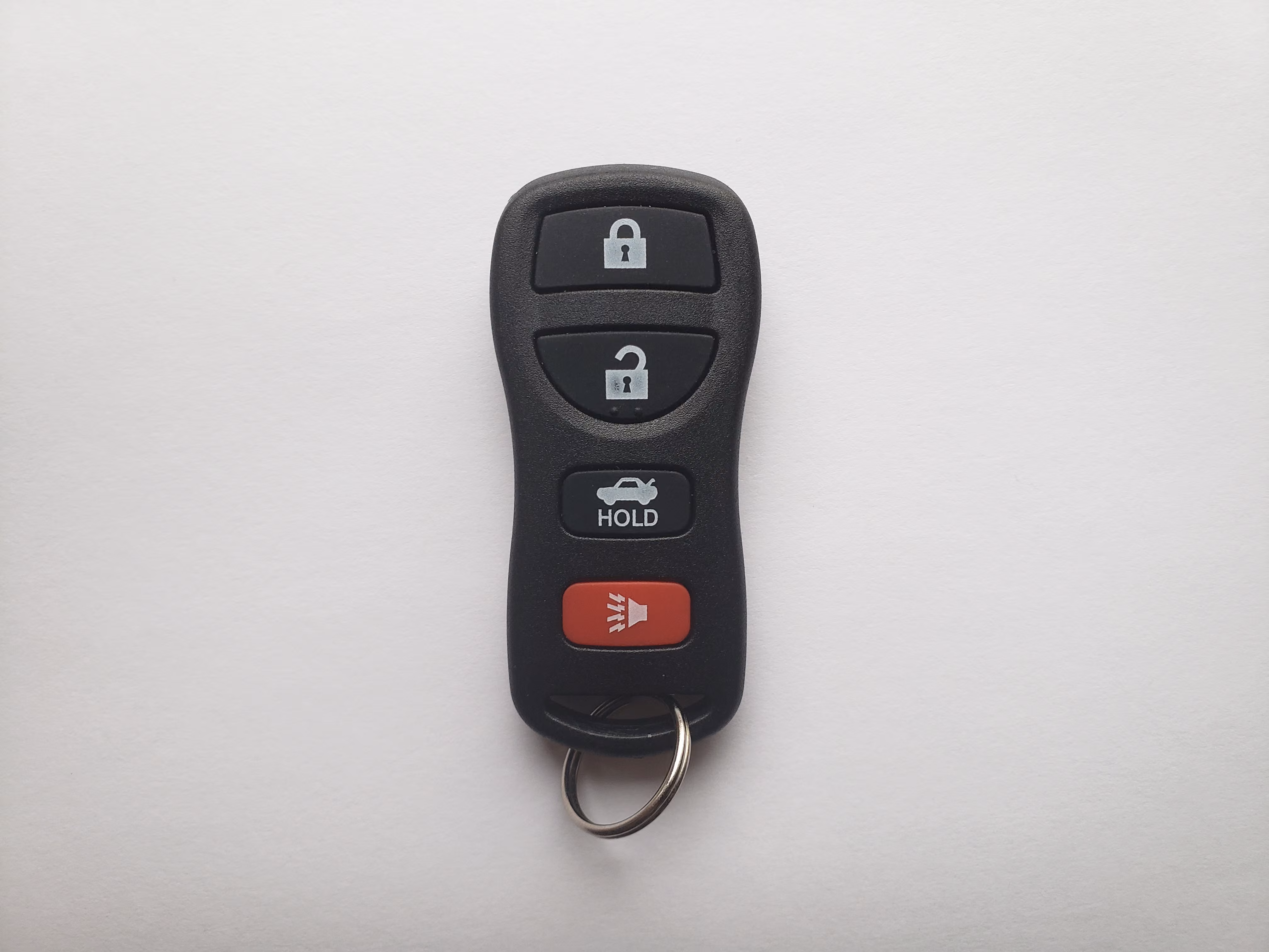
I got my first car a few months ago - a decidedly beat up North American 2005 Nissan Altima. It came with a remote keyfob, but something was shorting internally, and the battery would drain within a matter of hours. I ordered a two-pack of aftermarket fobs from Amazon, paired them no problem, and that was that.
After a while though, I got to thinking, how might I connect my car to my Home Assistant system? I am reluctant to tap into the CAN bus directly, so instead I am going to investigate utilizing the same method as my remote fob. Specifically, I want to program my own “fob” using an Arduino and a RF transmitter (spoiler: I cannot, at least for now).
The Hardware

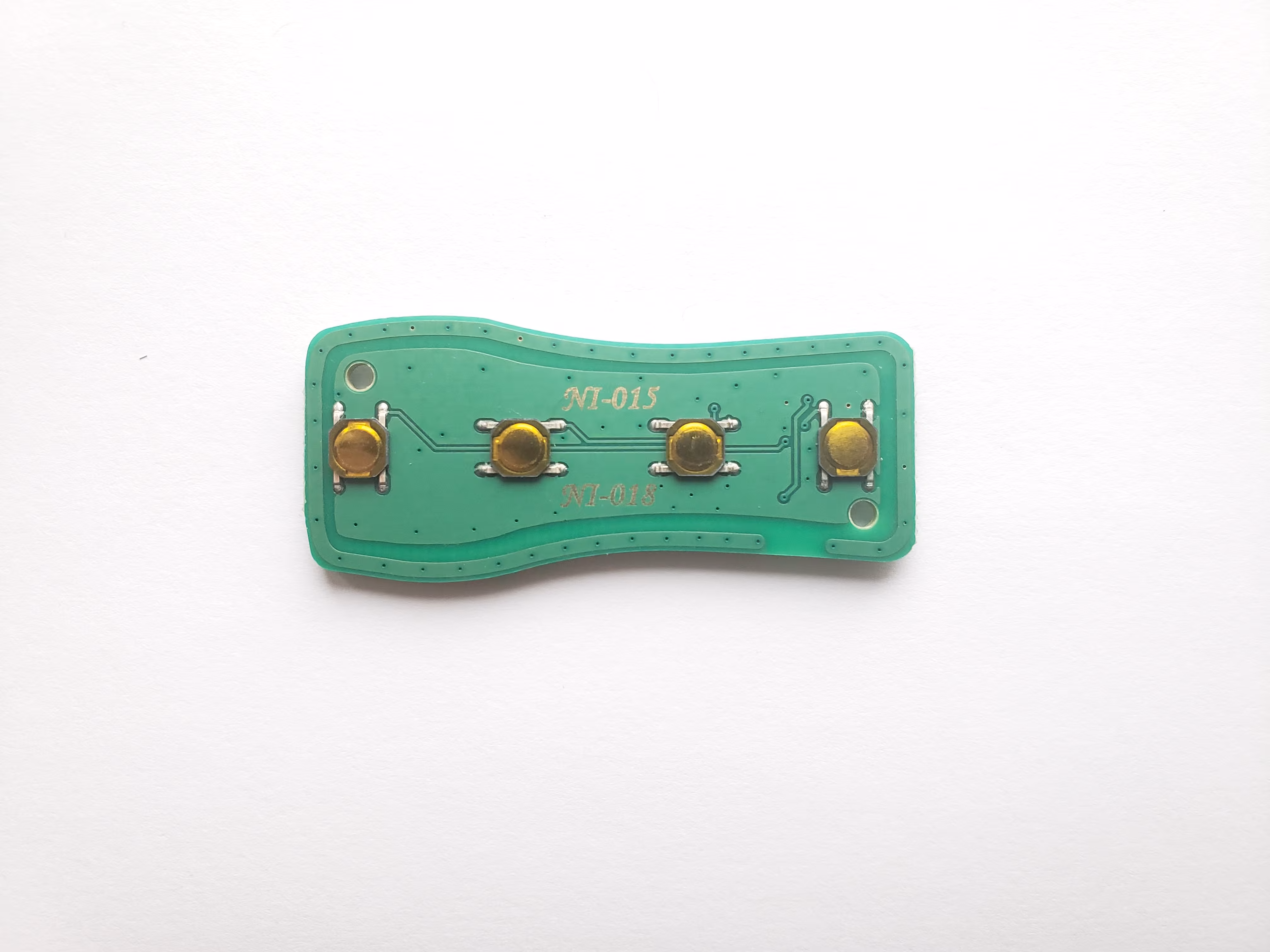
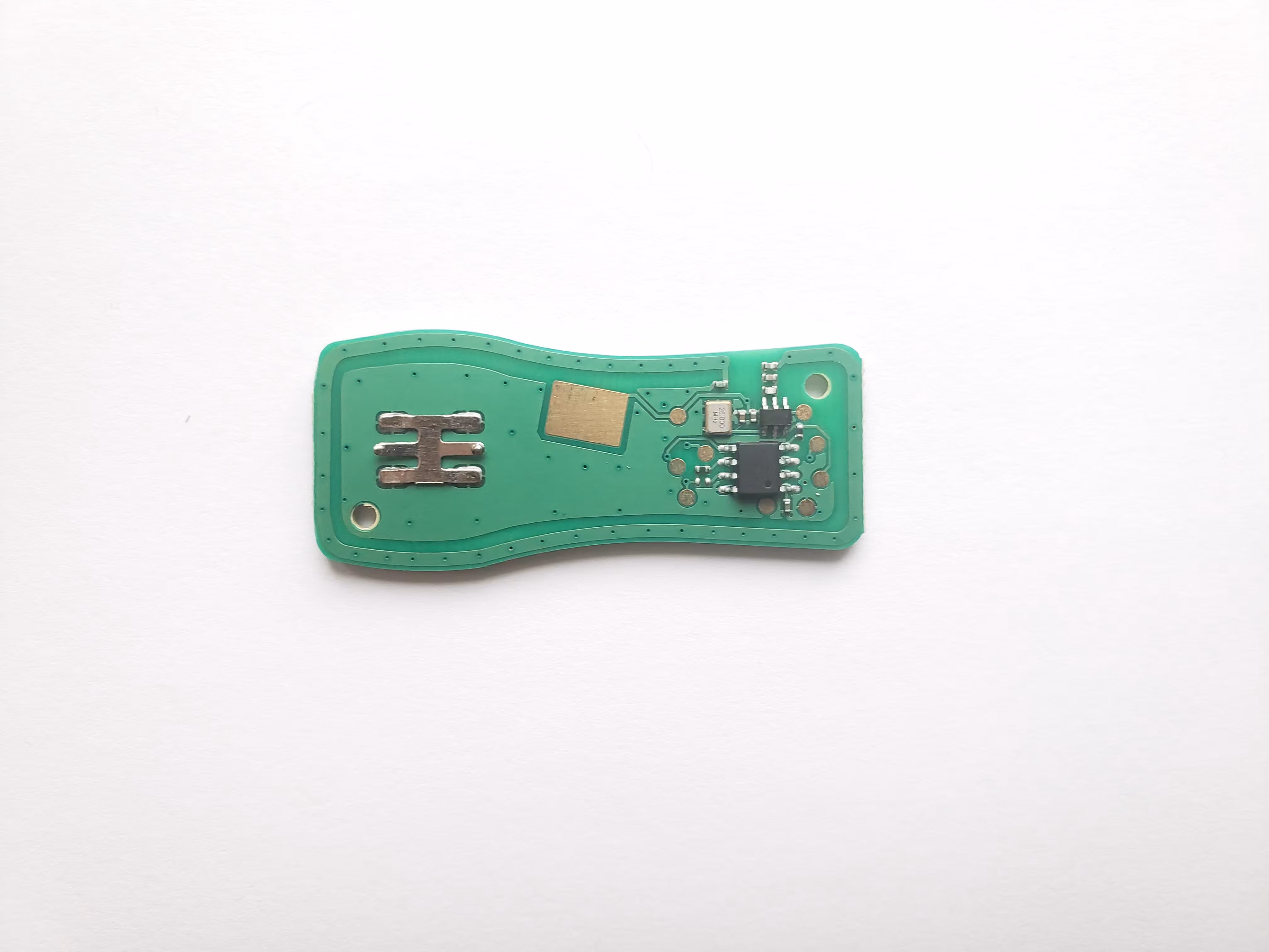
While I may analyze the original fob at some point, for the time being I shall work from the aftermarket fob. Opening the casing reveals a rather simple circuit (front, back) - battery contacts, four buttons, a smattering of passives, an oscillator, the main control chip, 8 test points, and an antenna trace running around the perimeter of the PCB.

Rather unhelpfully, the control IC is unmarked, so either I’ll need to wait until I can look at the original fob to find any clues, or try to find what I need online.
As a note, it should be easy enough for me to replace the buttons with an electrical solution controlled by an ESP8266 or similar - I may end up doing this some day. For the time being, however, I have nothing to glean from the hardware in my fob.
Research
A quick look at the Amazon listing for my fob already tells me what models of fobs it replaces: KBRASTU15, CWTWB1U758, and CWTWB1U821. Matching other listings, my specific model is the KBRASTU15. This is actually an FCC ID, so that’s my next lead.
This fccid.io listing is rather useful, providing original FCC images and documents. Unfortunately, the internal images are low enough resolution to prevent reading the IC silkscreen. Interestingly, the aftermarket fob has a small fraction of the part count of the original fob, while still functioning perfectly. The most useful available document is the Technical Description. This is where we start to get somewhere.
In essence, the fob emits a wakeup sequence ‘A’, followed by sequence ‘B’ repeated as long as the button is pressed. The structure of these sequences is also described - sufficient to say, it uses a rolling code system. Importantly for my analysis, the encoding method of the signal is given (though interestingly their diagram annotations seem to be incorrect).
With this information in hand, I ordered a cheap RTL-SDR (a Nooelec NESDR Mini 2+).
SDR Analysis

The radio, being a North American model, operates at 315MHz. Using Universal Radio Hacker, I began capturing examples of locking and unlocking signals. Using the software is outside the scope of this post, but I found some YouTube videos by the software author that proved to be useful - it’s not hard to learn to use.
Ultimately, I ended up trimming down 4 ‘B’ sequences each of locking and unlocking (that is, different presses, not repeats during the same press). I also opted not to include the preamble and header of these ‘B’ sequences, as these are the same for any fob and include no actual information.
The resulting signals varied in length and followed no apparent repeating format - this is where the encoding scheme described in the FCC documents comes in. Fortunately, URH allows specifying and chaining encoding schemes, as well as calling external software to decode the data. As I am not dealing with a large amount of data, I wrote a quick bash script to decode the data:
#!/bin/bash

lc=''

while IFS= read -r -n1 c; do

        if [ "${c}" == '' ]; then
                break
        fi

        if [ "${c}" != "${lc}" ] && [ "${lc}" != '' ]; then
                echo -n "${lc}" # Deal with the last character
                lc="${c}"
        elif [ "${lc}" == "${c}" ]; then
                if [ "${c}" == '0' ]; then
                        echo -n '1'
                else
                        echo -n '0'
                fi
                lc=''
        elif [ "${lc}" == '' ]; then
                lc="${c}"
        fi

done <<<"${1}"

exit
This does the trick, and all the data has a uniform length of 67 bits. While the document specifies 66 bits, perhaps the aftermarket keyfob adds an extra bit. In any case, this extra trailing bit is always 0.
Finally we have something like this:

The top four entries are when locking, the bottom four when unlocking. The highlighted segments from left to right, as per the technical document, are:
- encrypt
- serial number
- function code
- verify code
It can easily be seen how the intent of the button press is not encrypted, but is part of the function code near the end. Also, the serial is correctly defined, as it does not change at any point. I am not sure what the verify bits are present for - perhaps if an error occurs the encoding scheme would result in a non 0 result (though this is purely speculation).
What we know now is that the keyfob does indeed use a rolling code algorithm, though not which one (web searches do not seem to specify).
More Research
I do not have access to the original keyfob at this time, so some image searching may be in order. Several leads appeared, but the main one was this:

None of the text appears especially legible, so the first thing I can do is compare the logo on the OEM fob to existing rolling code chip manufacturers. As it happens, Microchip is the company in question, producing the widely documented KeeLoq product line (leaked spec sheet). Looking at their product lines, it becomes clear that the original fob uses the HCS361 chip. My aftermarket chips must be using a knockoff or unmarked version of this.
Hurray, we know what chip we’re up against, what algorithm it uses, and how to get the information of an existing fob. What we do not know is how to program our own chip (or software equivalent). This is where things get a lot more involved than I have the expertise to do.
What would be required would be the Nissan manufacturer code for this series of fobs. Try as I might, these do not seem to have leaked online, nor have any other manufacturers as far as I can tell. Speculating, perhaps those that have access to these codes either keep them to themselves for ethical reasons, or because there is financial incentive to keeping this information private. Clearly there are Chinese manufacturers who know what this key is, because it would have been required in order to program this fob.
Key Problem
So how might I find this manufacturer key? Curiously, I cannot even find reference to Nissan ever using KeeLoq, so that does not bode well. Trawling the recent NA Nissan git leak doesn’t reveal anything related to such a key. The consensus seems to be that a power analysis of the receiver is required to determine the manufacturer key. While apparently not difficult for the researchers, it is beyond my means at this stage. I am certainly not the first one to try this.
The way forward would seem to buy a spare ECU for my vehicle and to use a ChipWhisperer and attempt to learn how to do power analysis. I don’t have the time or resources (or frankly the need) to do that for now, so I think this is where my journey ends. I’ll update this if ever I can get my hands on the manufacturer key and do anything more with this.