 Views and opinions of the author are independent of employers past or present. Duh...
This is nothing too special really - I wanted to try my hand at designing a custom PCB and assembling a device from scratch. GitHub for this project.
This story actually starts a while ago (perhaps 2015), when I got the desire to build a DJ control panel (with no knowledge of how to get into it). This never really happened, but it did lead me to get to know some DAW software, and experiment with it off and on. But in the back of my head I still wanted to build some hardware to help with this.
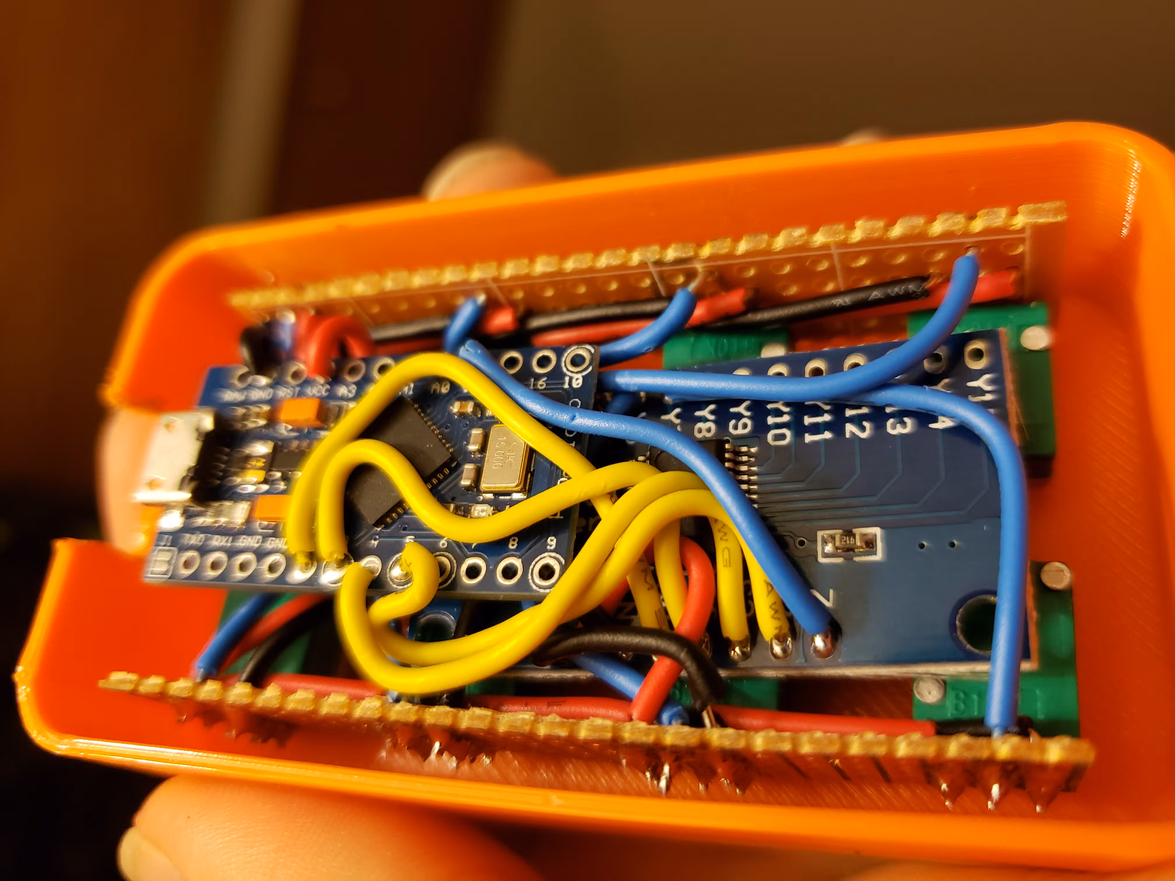
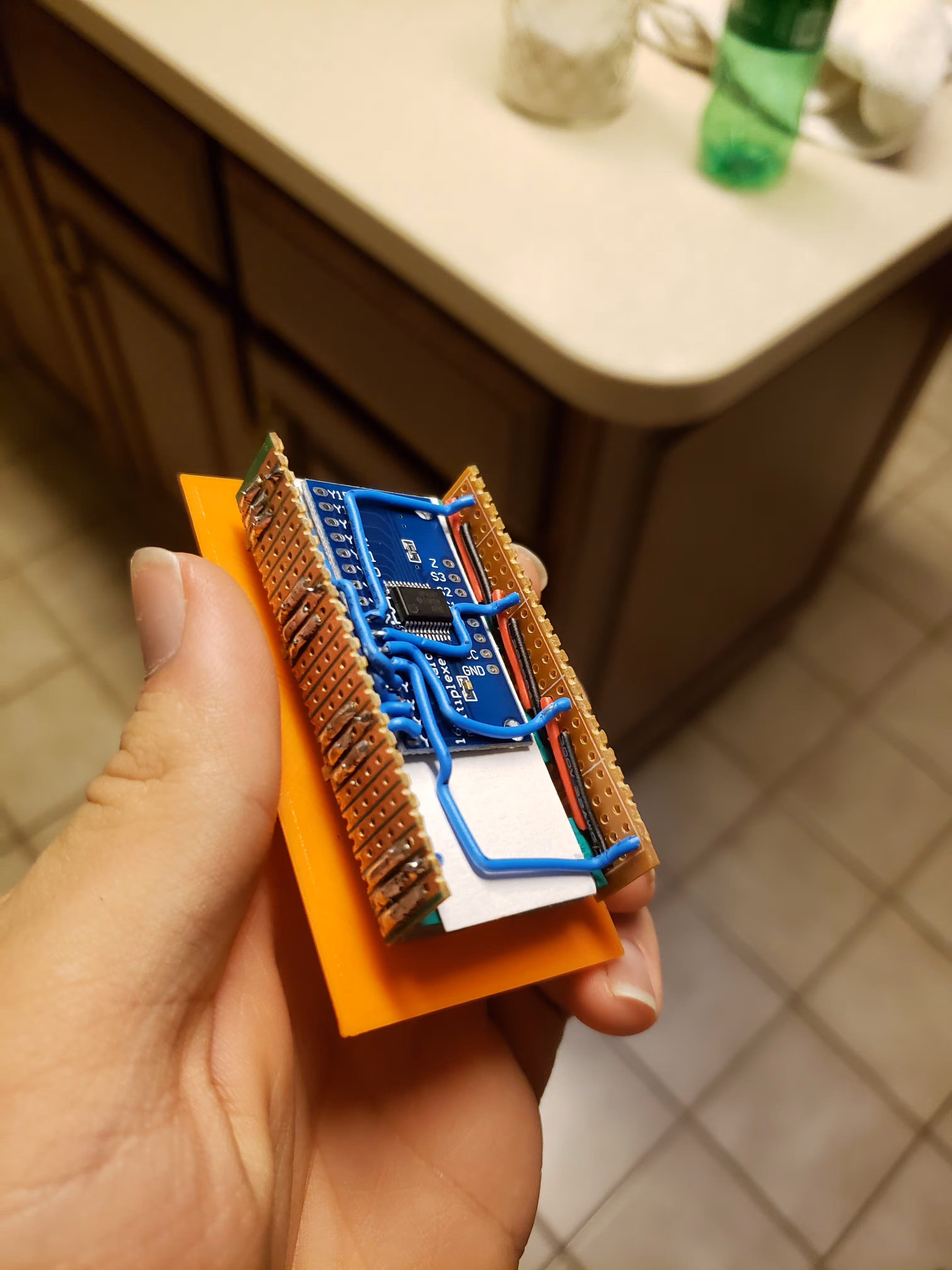
 This eventually came about in the summer of 2019, when I finally hand-wired a simple 8 knob control surface.
Truth be told, I actually built two.
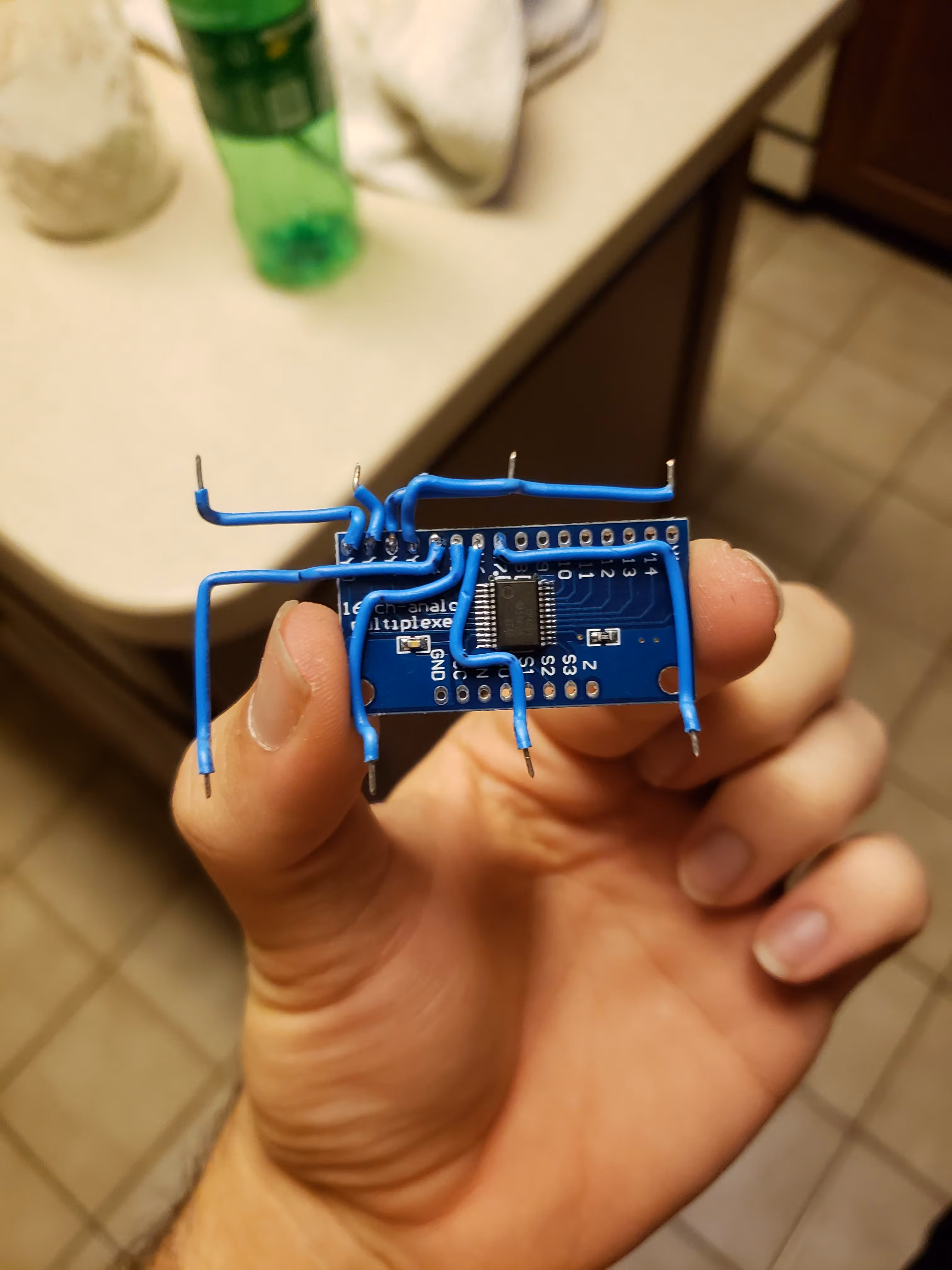
The first one had some issues (I wonder why…?), and would sporadically jitter values.
The second one worked correctly, having been wired much more carefully.
This eventually came about in the summer of 2019, when I finally hand-wired a simple 8 knob control surface.
Truth be told, I actually built two.
The first one had some issues (I wonder why…?), and would sporadically jitter values.
The second one worked correctly, having been wired much more carefully.
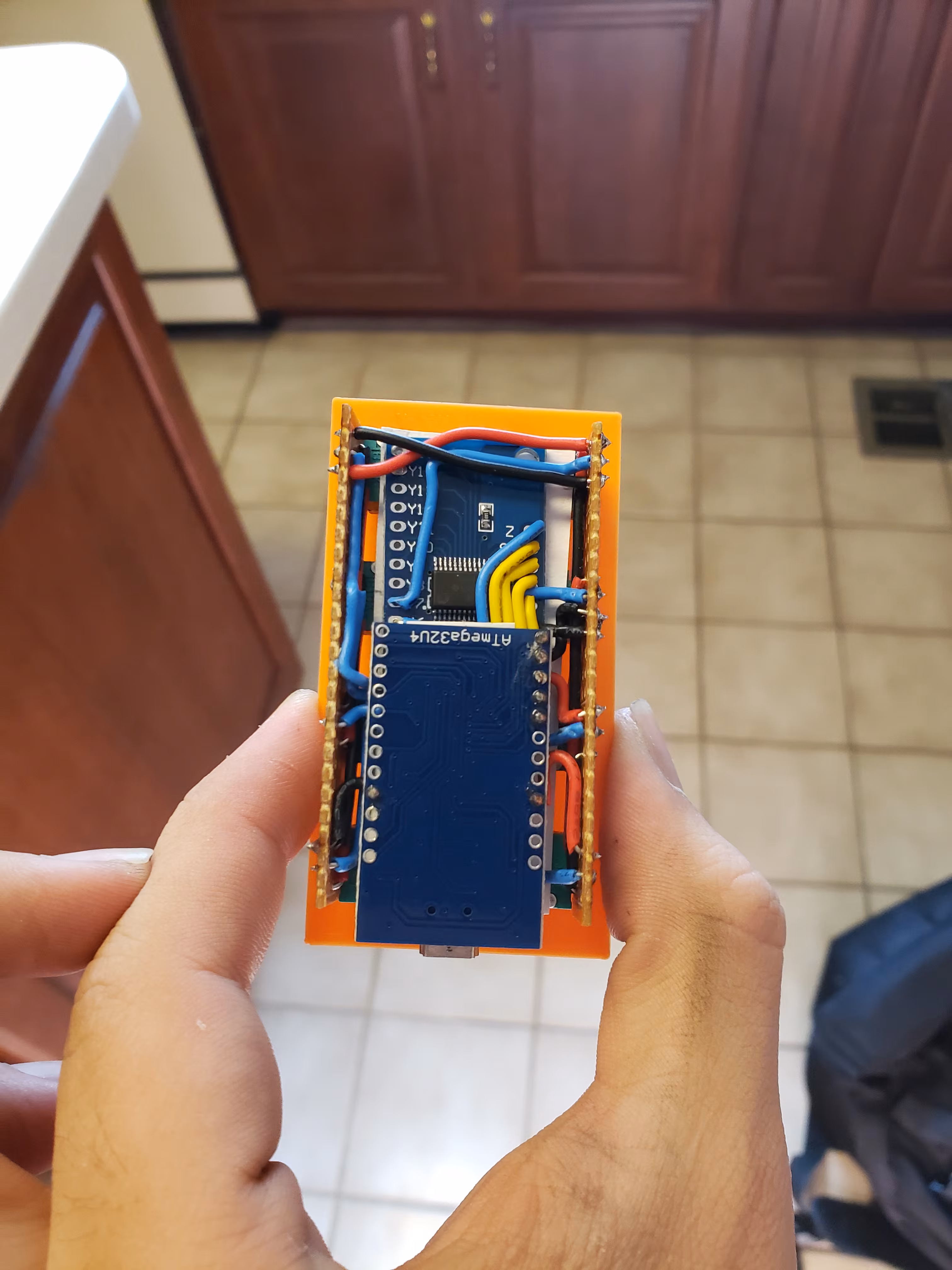
Still, it was lacking professionalism, polish, and most importantly, robustness. The sandwich of 22AWG wire, cardstock and PCB was less than sturdy, so I promptly packed it away and never used it. Around this time also, I tried very briefly to learn how to use KiCAD, but didn’t get far at all. This would come to change, however, in April of 2020.

 Fast forward close to a year, and here we are - toilet paper is the currency of the quickly collapsing Covid19 crazed world, and I’m back with my grandparents for the remainder of my semester (which, as of writing, is all but concluded).
Finding my lack of a social life leaving me with a little bit more free time, and being home yielding a lot more distractions, I learned the basics of KiCAD from YouTube, and set out to design a simple PCB.
My old MIDI controller project came to mind, so I set myself to it, and within a few days had my first Gerber files sent off to JLCPCB.
In reality, I should have waited a bit and done a couple more design iterations before committing, but I guess $7 is the price of impatience.
Fast forward close to a year, and here we are - toilet paper is the currency of the quickly collapsing Covid19 crazed world, and I’m back with my grandparents for the remainder of my semester (which, as of writing, is all but concluded).
Finding my lack of a social life leaving me with a little bit more free time, and being home yielding a lot more distractions, I learned the basics of KiCAD from YouTube, and set out to design a simple PCB.
My old MIDI controller project came to mind, so I set myself to it, and within a few days had my first Gerber files sent off to JLCPCB.
In reality, I should have waited a bit and done a couple more design iterations before committing, but I guess $7 is the price of impatience.
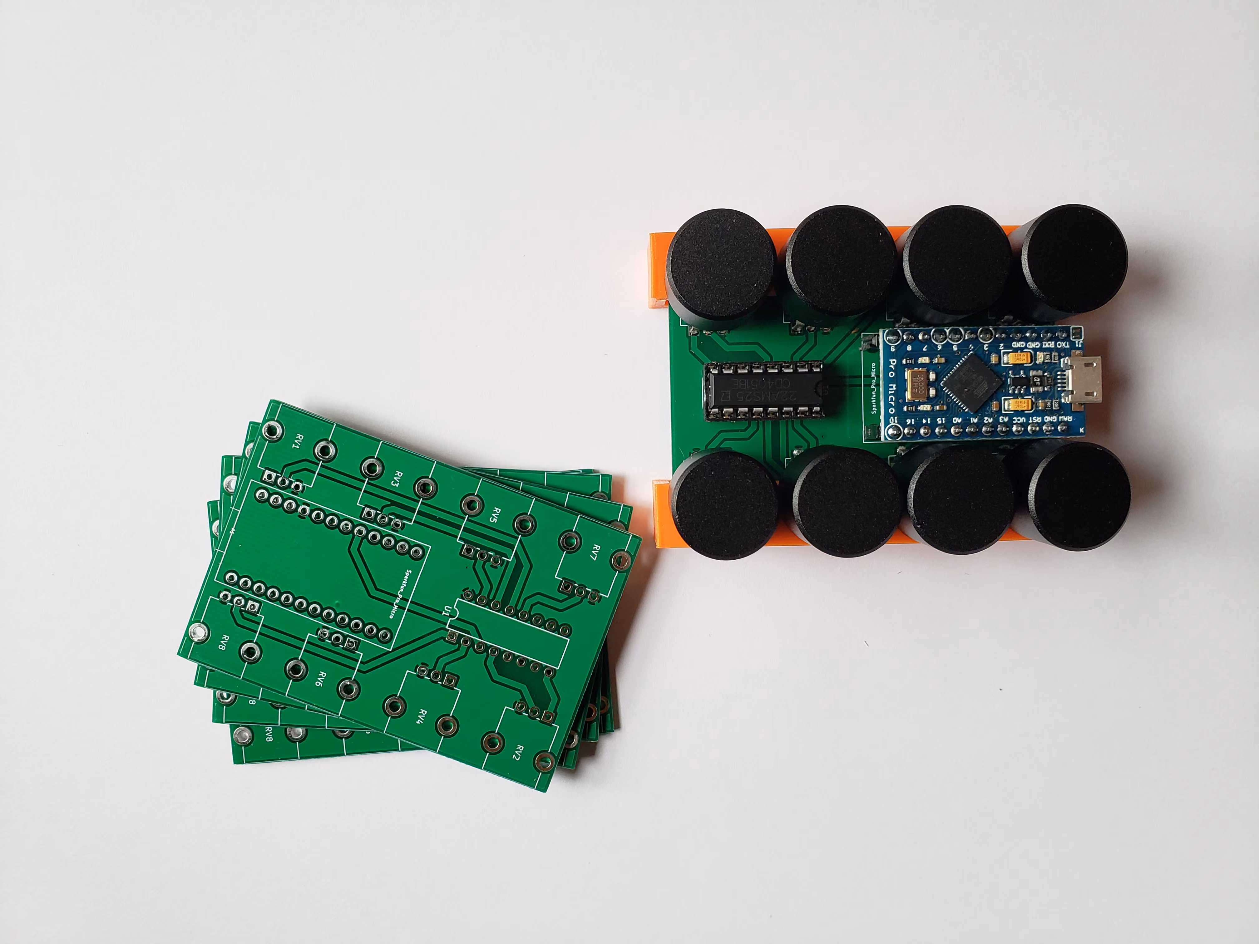
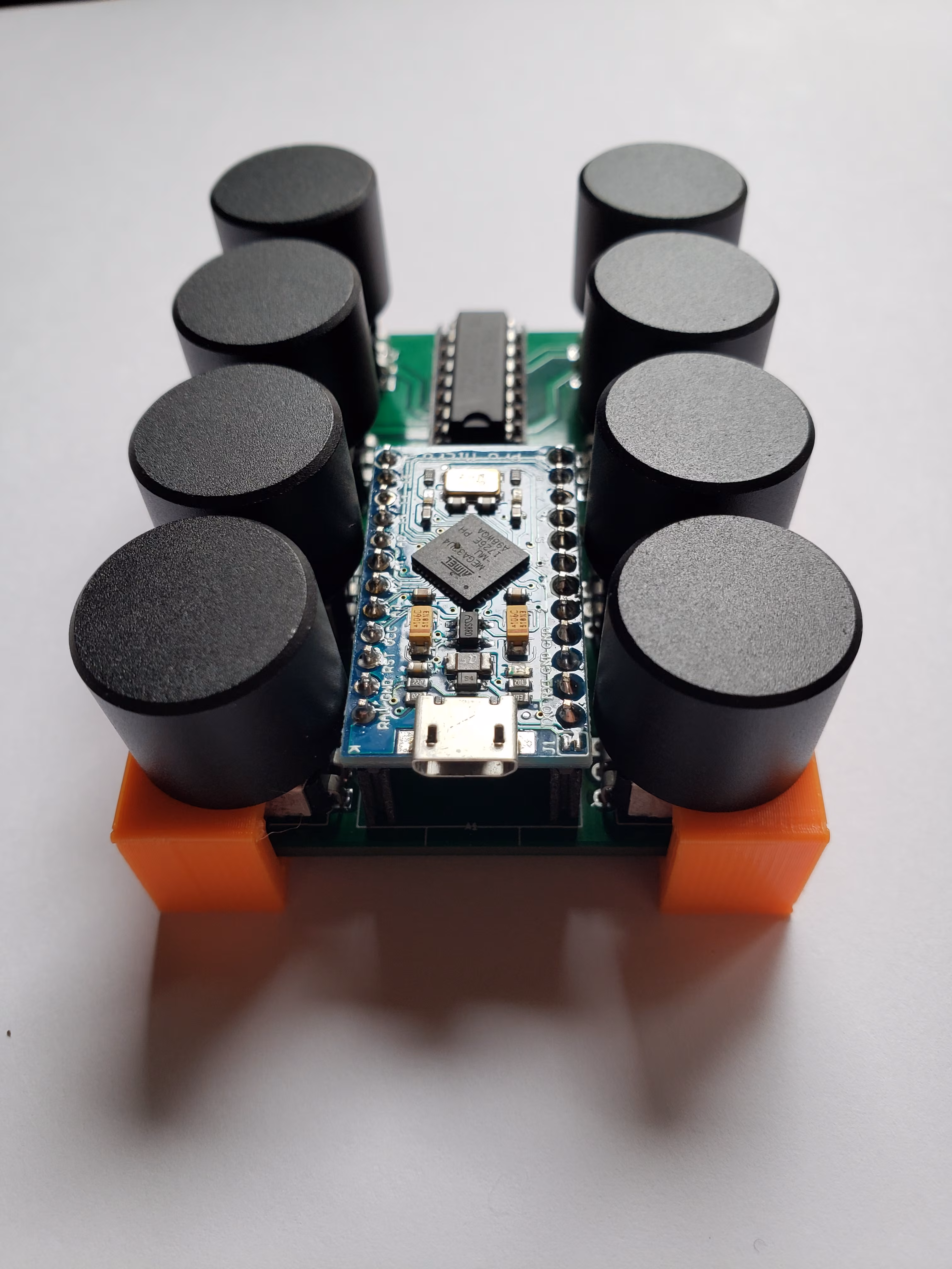
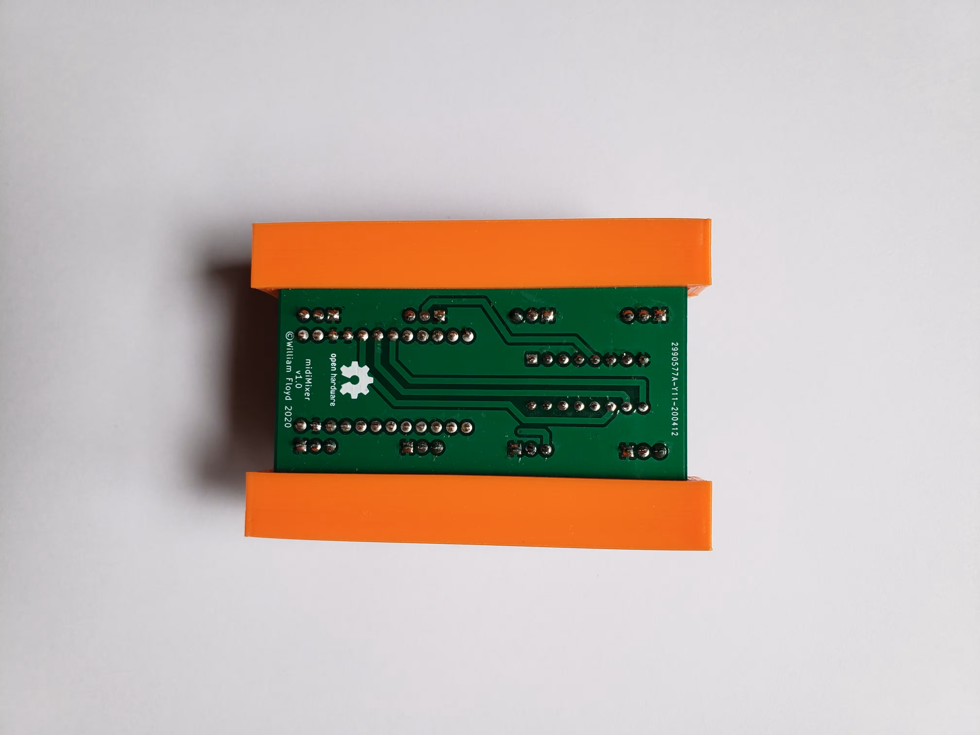
 So it was that my crisp PCBs showed up 3 weeks later - I had one assembled within the hour, and my old code dusted off and flashed within two hours.
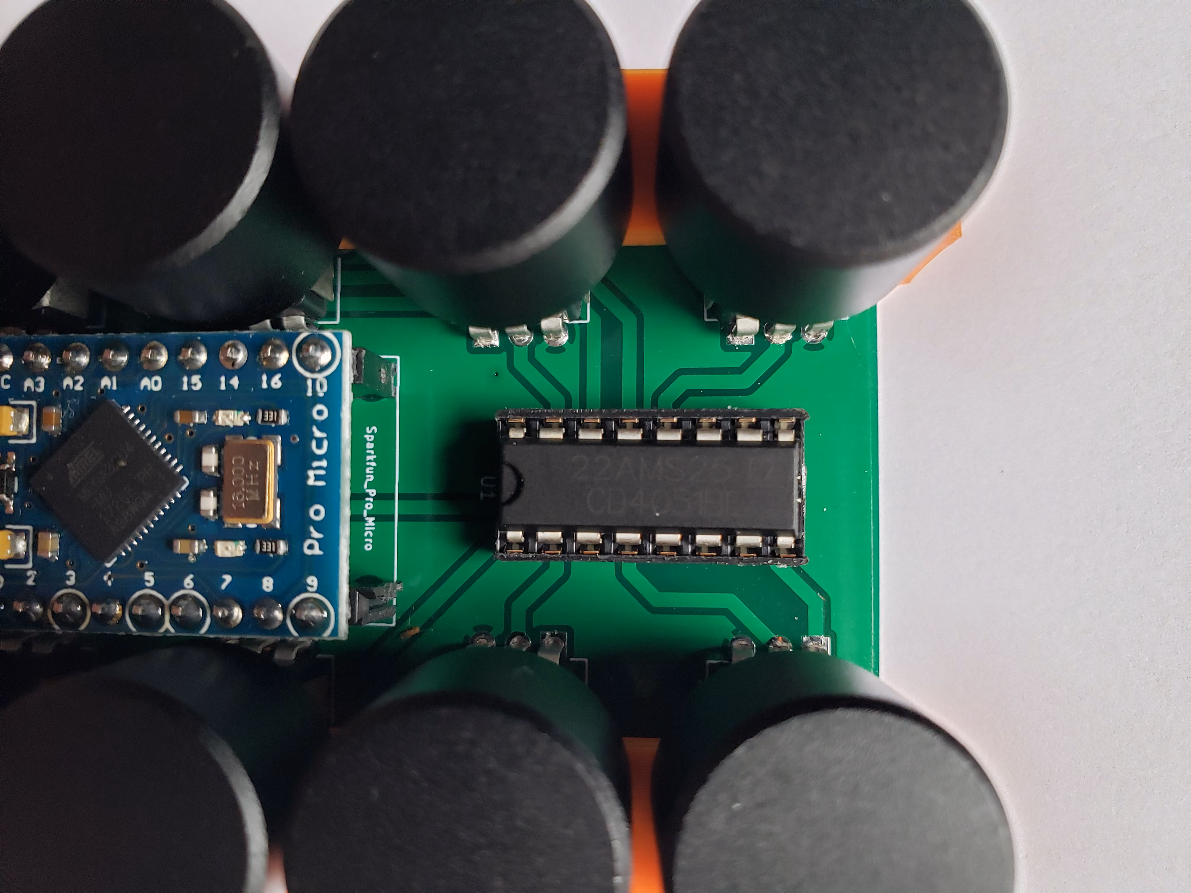
It’s really as simple as it gets - a Pro Micro hooked up to a 4051 analogue multiplexer, in turn hooked up to 8 potentiometers.
So it was that my crisp PCBs showed up 3 weeks later - I had one assembled within the hour, and my old code dusted off and flashed within two hours.
It’s really as simple as it gets - a Pro Micro hooked up to a 4051 analogue multiplexer, in turn hooked up to 8 potentiometers.
The potentiometers I had on hand ended up being a bit different than the footprints I had used, so I ended up having to clip the mounting tabs off of them. This, as one might imagine, made them extraordinarily flimsy, so I designed and printed a couple clamps to align and hold solid the potentiometers. These also have the added benefit of keeping the soldered pins off of whatever surface the mixer is on. Should the correct potentiometers be used, these would not be needed, though some feet or a case for the PCB would still be best.
 This being my first PCB design, I am quite happy it worked out so well - I am studying for Mechanical Engineering, not Electrical…
However, I see room for improvement.
The potentiometers are too close together, and the rows are too far apart.
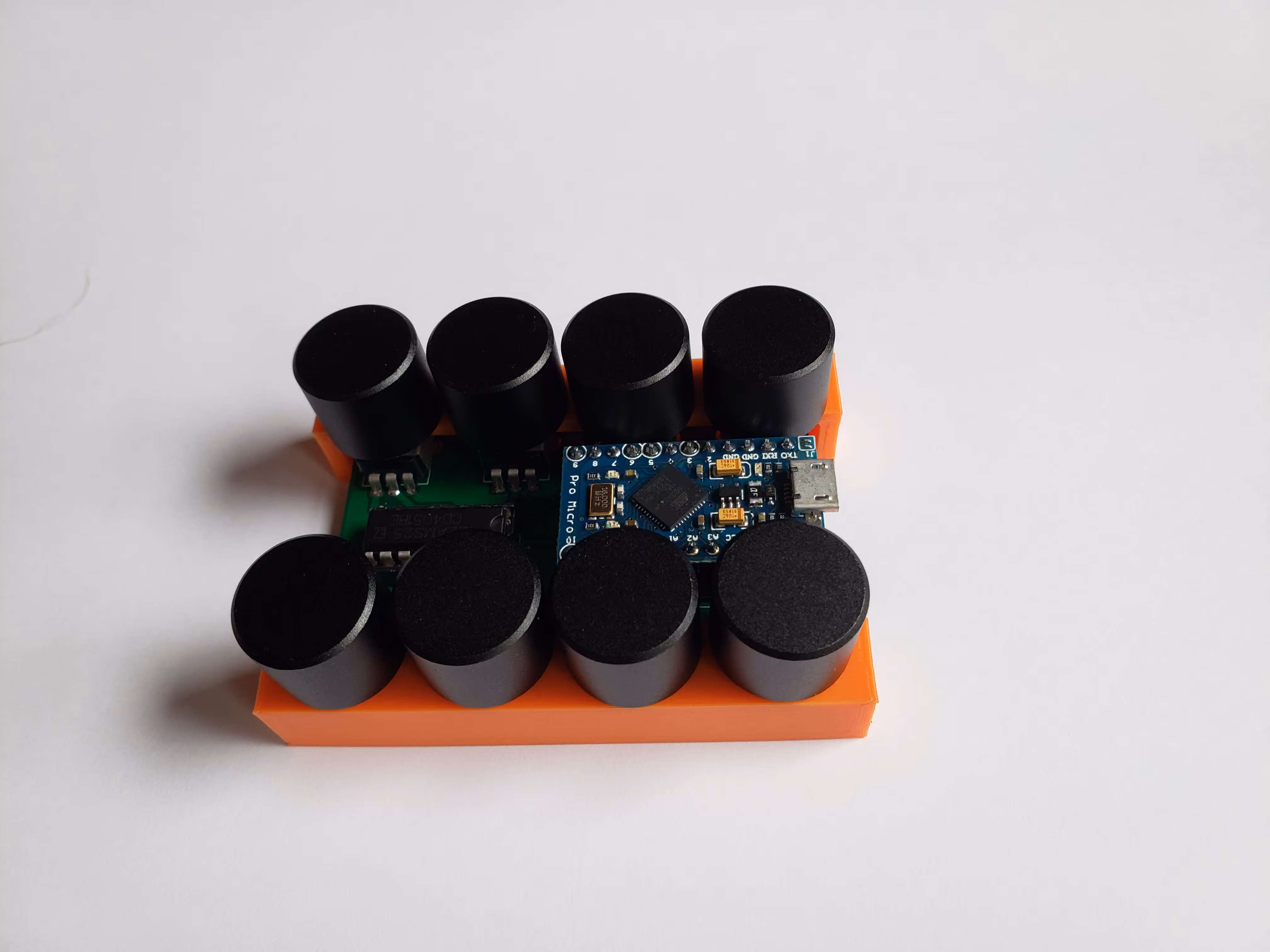
The knobs barely clear the Arduino, and the Arduino is mounted far higher off the PCB than I would like.
I see myself making a v2 in due course - perhaps next time I will try JLCPCB’s SMT assembly?
I imagine adding indicator LEDs, improving the layout, and adding a button to switch between banks would make this much more useful.
This being my first PCB design, I am quite happy it worked out so well - I am studying for Mechanical Engineering, not Electrical…
However, I see room for improvement.
The potentiometers are too close together, and the rows are too far apart.
The knobs barely clear the Arduino, and the Arduino is mounted far higher off the PCB than I would like.
I see myself making a v2 in due course - perhaps next time I will try JLCPCB’s SMT assembly?
I imagine adding indicator LEDs, improving the layout, and adding a button to switch between banks would make this much more useful.
